PAGE 83a – March 2009 SPECIAL MID-MONTH BONUS ISSUE
H O T I D E A S F O R S M A L L R A I L R O A D S
Depite having reviewed just two months ago a number of excellent updates to past layouts (or maybe because we did), I’ve received many new updates since Scrapbook #81 was published. The revamps are often both interesting and inspiring, so here they are for you to ponder.
In This Issue
New York Harbor Belt—HO Trackmobile switching line
El Dorito Mine—New “takes” on a classic plan
On30 Mountain Line—A Christmas display reaches for a new level
Double Loco Lift Line—Using a Loco Lift as a 24-inch cassette
Three Loco Lifts—No waiting!
Abu Dhabi Road—Makiing progress despite heavy odds
Hillside—Scenery comes to Australian layout
The Real Coors Transfer Table—The real thing at Coors
CONTEST AWARD WINNER MOVES TO EXHIBITION CIRCUIT
Original Layout Updated Layout
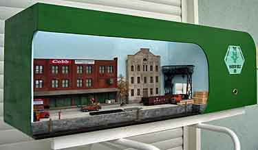
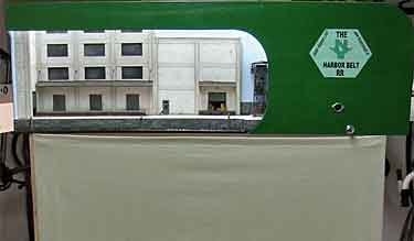
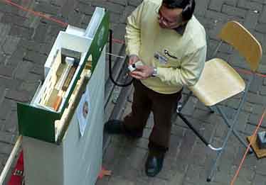
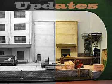
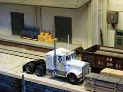
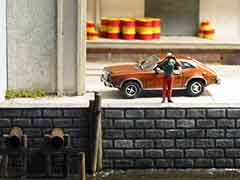
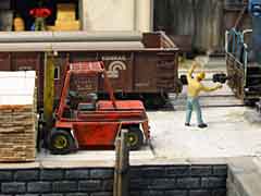
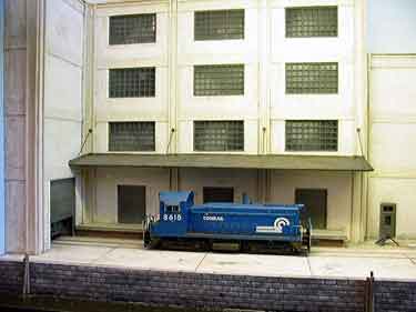
Alexander Lösch, from Elfershausen, Germany, originally created New York Harbor Belt RR as an entry in this site’s Trackmobile layout contest last year. He won a Distinguished Runner Up award. Subsequently, he updated and upgraded the NYHB as an exhibition quality display that had its debut last month at OntraXs, an international model exhibition held at the Spoorwegmuseum in Utrecht, The Netherlands. These photos show the changes from the original contest layout (upper left) to the updated work on display at Utrecht. There’s lots more to see at Alexander’s website.
Helping at the exhibition by operating the tiny layout was Alexander’s friend, Bernd Stiller (left photo).
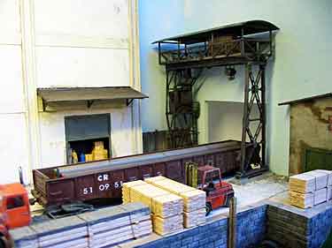
EL DORITO MINE — AN OLD TIMER IS REVIVED
One of the earliest and smallest micro layouts I’ve designed is El Dorito Mine, which measures at most 12x2in (30x5cm) in Gn15 or On30 scale. Featured (and the only) operation is bringing the tailings (waste) out from the minehead and dumping them—a limited, but prototypically accurate activity. Suddenly we’re experiencing a revival of this venerable layout, with a variety of new twists. This report outlines current developments. —Carl Arendt
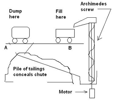
John Hubbard, from Huntsville, Alabama USA, is considering using a microprocessor to automate the whole operation. He sent along a diagram (right) of his incipient layout, explaining, “Here’s the sequence:
“1. The loco pulls the V-skip out of the mine entrance until it trips reed switch A concealed just under the track in the trestle structure. The reed switch signals the microprocessor to shut off the track power and actuate the tipping mechanism. The tipper is operated by a small R/C type servo located below the ‘ground’ level and turning a shaft concealed in one of the legs of the trestle. The load dumps into a chute that actually is concealed inside a pile of ‘tailings.’ The chute leads down and back to the rear of the layout.
“2. The microprocessor reverses the polarity of the track and turns the power on so that the loco pushes the V-skip back into the mine entrance, where reed switch B closes and the microprocessor shuts off track power again.
“3. With the tipper in the Load position, the microprocessor turns on the motor operating the Archimedes screw. It remains on for a measured amount of time—enough to fill the tipper but not to overfill it—then shuts off. Other effects operate at the same time, like the wheel on top of the minehead (representing the elevator that lifts the load to the surface), klaxon, and flashing light.
“4. When the Loading operation is complete, the microprocessor again reverses the polarity on the track and turns on the power. Go to step 1. I’ve simulated most of this by hand. I used a ½in (12mm) bit from my ‘brace and bit’ inside a brass tube and raised HO scale track gravel about 10 inches with no problem.” We’ll keep you posted, folks!
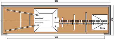
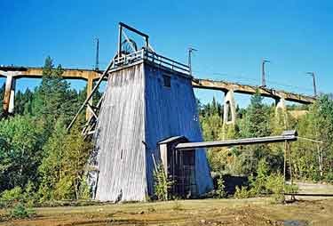
While pawing through my El Dorito file, I found this diagram and photo (left below) from somewhere in Norway, proving that there’s a prototype for everything! The photograph seems to show a prototype setup with very similar geometry to the El Dorito layout design, and the plan shows a model version. I’m not sure who is responsible for this… if you’ll get in touch, we’ll add the appropriate credit line! Has anyone actually built this proposed model?
And one other photo surfaced (below)—this “secret” draft layout from the Antipodes. Watch for more! —Carl
FORMER CHRISTMAS RR GROWS UP… AND UP… AND UP


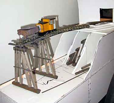
A couple years ago, Lars Knapp and his father Larry, from Charlotte, North Carolina USA, built a charming little Christmas micro layout in On30 scale. It was shown in Scrapbook #59. Last summer they decided to raise its sites considerably… and so they did, adding a mountain range of generous proportions (in O scale!). The additional scenery even concealed the rear fiddle track (lower photo). The father-son team also added a small amount of On18 (O scale on 9mm track) trackage to provide a mining railroad flavor to the scene (just visible in the top photo). Looks great, doesn’t it? Now they’re contemplating even more drastic surgery… we’ll watch for the results!
HOW TO USE A DOUBLE LOCO LIFT AS A CLEVER CASSETTE

Shortliner Jack Trollope, from the Highlands of Scotland, asks a provocative question: “How do you squeeze a 63x12in [160x30cm] layout, including fiddle yard, into a 40x12in [102x30cm] space?”
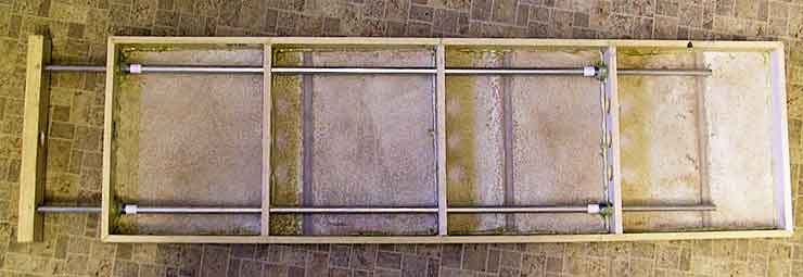
And he answers it himself. “You build a layout with a collapsing fiddle yard! This H0 line uses the double length Peco Loco Lift [described in Scrapbook #80] for the fiddle yard. The track shown (above) has just been laid into position to see if it fits; ignore the bits that stick out to the right. There will be a short length of track on the end of the extension for the Loco Lift to sit on. It will have ‘belt and braces’ power supplied through the telescoping aluminium tubes, and the other end will pick up from the main trackage.
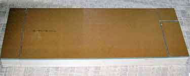
“This benchwork (below) is for my (hopefully upcoming) Urban Belt Traction layout—UBT being my lady’s initials. The top surface is an off-cut of flooring material from B&Q (a DIY store like Home Depot in the U.S.), turned underside upwards. The side in this shot has a tile pattern built into what would normally be the top surface. The whole thing is assembled with polyurethane glue, which is stronger than the wood. There are two small, removable veneer pins through the wooden end and through two drilled holes in the extension tubes, just to make sure they stay put (they are epoxied into place) otherwise no screws or nails have been used.
“The layout would be a very small freight yard ‘under wire’. Probably a flat warehouse at the rear, a freight house at the left end of the centre track, and a team track at the front—all possibly in a ‘trench’ with a highway bridge at the left.” Sounds like a good plan… we’ll keep you posted!
YOU CAN NEVER HAVE TOO MANY LOCO LIFTS!

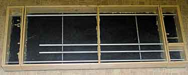
Not being given to let a good idea stand idle, Shortliner Jack Trollope has devised a layout plan that uses three Peco Loco Lifts as fiddle yards, in conjunction with aluminium tubing (as described above)! The track arrangement here is one that Jack originally presented in Scrapbook #78a under the heading “Check out the rotating sector plates,” but with the original sector plates replaced with Loco Lifts. In this case, two of the lifts are used ‘from the box’ at 12in (30cm) long, the other is cut down to half size. The main layout measures 21½x8½in (55x22cm).
The two photos below show details of the construction which are similar to the Urban Belt Traction construction discussed above. This layout could also run “under wire” and function as a traction freight yard. It certainly makes extensive use of the idea that Loco Lifts can function as excellent fiddle yard cassettes!
PROGRESS REPORTED FROM LAYOUT A-BUILDING IN ABU DHABI
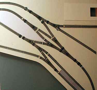
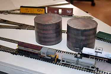
Norman Woollons, from Abu Dhabi, United Arab Emirates, sent an update on his Five Ways Quay N-scale coffee table layout, first seen as a drawing in Scrapbook #70. Trackwork (right) has now been laid, tested and wired, with some small changes from the 2008 drawing. Beginnings of scenery have appeared (above). Next tasks: building a 10-lever frame to control turnouts, and adjusting positions of rare earth magnets to accomplish automatic uncoupling. Stay tuned!
SCENERY APPEARS ON THE ‘WINDOW SHELF IN OZ’
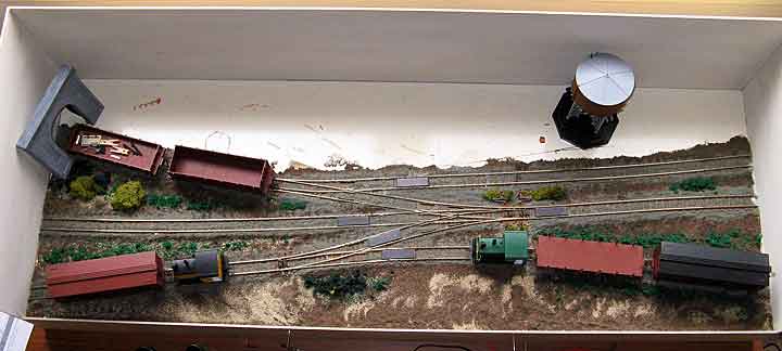
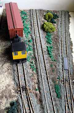
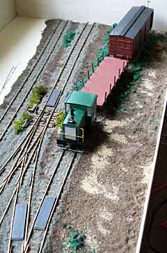
Scott MacLean, from Melbourne, Australia, is adding scenery to his window-seat layout, now called Hillside, that was first reported in Scrapbook #77. The name recalls an HOn30/H0e layout he built 15 years ago!
Additions have included much work on the eletrics, like using micro switches to operate the three-way turnout plus DCC control of the two On30 Bachmann switchers, as well as ballast from various roadside locations in Victoria. Biggest current project is creating a backscene (example below) from a series of panoramic photos he’s taken. The rest of the rear scenery will then be blended into the backscene.

WILL THE REAL COORS TRANSFER TABLE PLEASE STAND OUT?
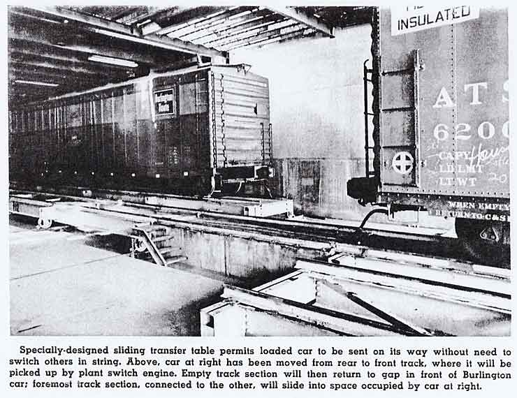
Prolific layout designer Mike McLaughlin, from Denver, Colorado, has been responsible for some of the most innovative designs presented on these pages. Perhaps his best-known effort is A Pony Keg of Coors, a layout that spotlights the intriguing “double transfer table” loading system used at Coors Brewing Company’s beer-making facility in Golden, Colorado USA. Recently Mike found an old copy of a Burlington Railroad employee magazine that featured a short article about Coors and a photo of the tables and how they actually work (below).
Mike commments: “The Q car is on the ‘loading’ table back against the door in the warehouse wall. The ‘main track’ table is in line with the lead. The ATSF car is on the loading table, but it’s pushed the main track table out of the way and is lined up to allow the car to be pulled.”
Leave a Reply