Standard Gauge Lines
As tight curves are likely to be a big issue on micro layouts,
most designs patternd after real places are built on shelves —
where curvature of the track is not an issue, but length of run is!
Take a look at some of the ingenious solutions to this problem
in this section, dedicated to layouts designed to fit on shelves
and modeled upon standard-gauge prototypes.
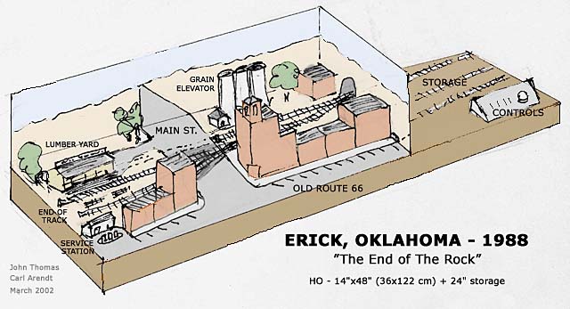
A real-life example of an Inglenook style layout can be found at Erick, Oklahoma, a tiny crossroads on the former Route 66 in the far west of the state, almost in Texas. After the Rock Island Line, beloved of many midwesterners, went under in 1978 the main line tracks were torn up in many places. But part of the line was preserved as far as Erick, to serve farming customers and a few others. So by 1985 the end of the line for The Rock was this trackage in Erick, Oklahoma — presented almost verbatim in this almost-micro bookshelf layout!
 Oklahoman John Thomas used to drive through Erick, just to muse on the remainder of the once-mighty CRI&P, and his nostalgic memories plus some joint research produced the impetus for this little plan. The track layout, Route 66, and the served industries are all shown as they are today. The visible part of the layout will (just) fit in a 14″x48″ shelf, with about a 24″ storage track at the right for “fiddling.” Inglenook switching games will work fine on this prototypical track pattern! And if you’re a Route 66 fan, warm up the Corvette and have a blast!
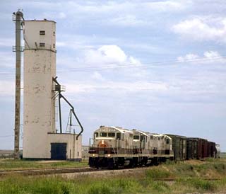
Present day rail service is provided by Farmrail. Typical FMRC GP10’s and one of Oklahoma’s ubiquitous grain elevators, are shown at right. Photo by Wes Carr.
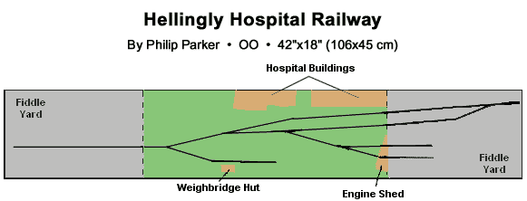
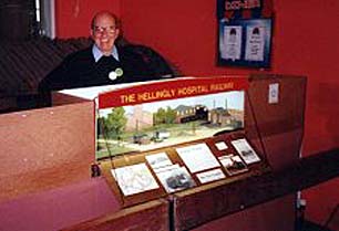
Philip Parker has researched and modeled a very small, nearly unknown but charming prototype railway in East Sussex — the Hellingly Hospital Railway. Originally constructed by the contractor who built a new mental hospital near Hellingly in 1902, the railway kept the same trackage, added an unusual overhead wire, and carried coal and passengers from the village of Hellingly to the hospital for over 50 years.
Rolling stock consisted of a small steeplecab electric locomotive (to haul the coal) and a tiny trolley car (tram). Phil’s models of both are pictured below. The visible part of the layout measures 42″x18″, with fiddle space at both ends. The HHR is on view at many English exhibitions, already booking for 2004!
For more information on both the prototype and the model of the Hellingly Hospital Railway, see Phil’s web site. This layout is an excellent example of the pleasures of modeling a specific prototype scene in the micro format.
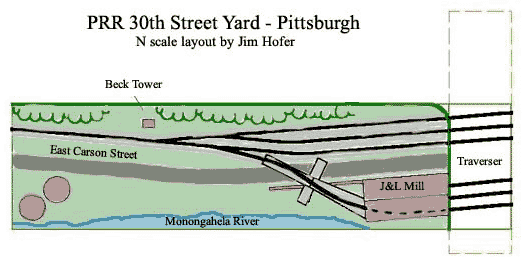 Way back when steel was still king in Pittsburgh, the Pennsylvania RR’s 30th Street Yard was the PRR’s main interchange with Jones & Laughlin Steel’s terminal road, the Monongahela Connecting (or MonCon). Jim Hofer has found a way to model that interchange point very accurately in N scale, in an area of 12×42 inches (30×106 cm). Operations can duplicate the prototype exactly — or the layout can be operated as a switching puzzle on the Inglenook pattern.
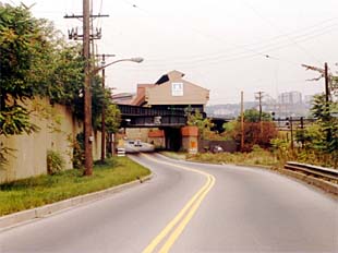
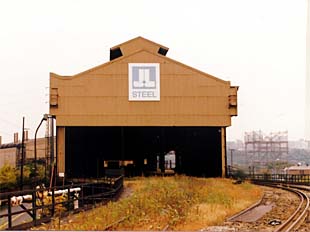
The prototype 30th Street Yard sat on a low bluff between East Carson Street and the hills to the south, with the MonCon interchange track crossing East Carson on a plate girder bridge to enter the J&L mill on the south bank of the Monongahela River. The MonCon track continued through the mill, and continuing at grade to cross the river on the appropriately named Hot Metal Bridge, reached the J&L blast furnaces on the north shore of the Mon.
Interchange traffic across East Carson Street involved loads and empties from both the electric furnaces on the south shore and the blast furnaces on the north shore. In the model, predominant traffic should be gondolas of scrap metal to feed the electric furnaces, along with covered hoppers of additives for the mills on both shores. Outbound loads would include finished and semi-finished steel shipping in gondolas, coil cars, and an occasional boxcar from the finishing mills on the north shore. From the coke works will come open hoppers of coke, along with tank cars of by-products. This traffic flow was nearly constant from the mid-1960s through 1979, spanning the PRR, Penn Central, and the early days of Conrail.
To manage this heavy traffic flow, Jim has designed an unusual backstage traverser (transfer table). It can help in moving cars on and off the layout, as well as exchanging cars behind the scenes between the J&L mill and the yard. Among other things, you can easily set up a “Loads in – empties out” pattern of car movement between mill and yard using the traverser. Each of its six tracks will easily hold two 50-foot cars with room to spare.
In addition to prototypical freight car movements, you can also use this versatile micro layout as an Inglenook switching puzzle. Each of the yard tracks comfortably holds three 50-foot cars, and the yard lead can accommodate two 50-foot cars and a locomotive (either the wide variety of ALCO locos or the later EMD SW1001’s used by the MonCon). By generating an outbound train consist from a switch list or by drawing tokens from a hat, you can set up a fascinating problem in car movement that will keep you and your friends occupied for hours!
What more can you ask? Jim has designed completely prototypical operations as well as an absorbing shunting game in a single micro-sized layout! To get you started, Jim took the two photos below after closure of the mill. On the left is the view of the plate girder bridge seen from East Carson Street, and on the right is a closeup of the J&L electric furnace mill entrance.
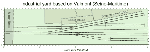
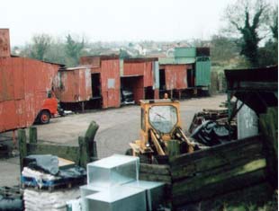
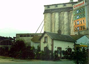 David Thomas has developed a delightful rural French industrial-switching layout based on a tiny, abandoned knot of trackage he found on holiday. Valmont is a closed but not yet dismantled switching location at one end of a small country station on the line between the ports of Fecamp and Dieppe in Normandy. David explains, “It’s so small that it couldn’t have handled more than six or seven wagons [serving the grain silos]. What makes it even more interesting is that the silo yard was shunted using capstans.
“Presumably the local freight train picked up full wagons and dropped empties in the front of the two sidings. Then the mainline point was closed and the second point was turned to the short yard lead so that wagons could be shunted to and from the loading bay using the capstan and a rope without fouling the main line. For the model plan, I’ve lengthened the yard lead slightly, and the yard is shunted by a small loco that never ventures onto the main line. An ambitious modeler might want to design a plan that actually uses capstans to do all the shunting.
“The two front tracks were the main line and the start of the station loop for Valmont station, which is on the other side of the level crossing to the right. These tracks could be used, along with the silo yard, to form Inglenook-style sidings shunted by the main line locomotive … with the twist that one of the sidings is itself a small shunting yard with its own loco or capstan shunting.
“I measured the real yard in September 2002 by pacing it out, and the prototype plan [below] is reasonably accurate in HO scale. The real location scales to about five feet by two feet, so I’ve used short radius points and reduced it in the micro model plan to 4 x 1 feet (and the width could easily be further reduced to 9 or 10 inches).
“At this time, the points are rusted into position, and the silos themselves have been taken over by a sort of supermarket chain for farmers called Point Vert that sells things like small tools and country clothing. The station building and crossing keeper’s cottage are still intact and in use as private houses, but the station’s main goods yard has been taken over by a supermarket whose petrol prices in Euros you can see in one of the photos [above].
“One thing this location demonstrates is the surprisingly large size of an industry that just generates a few wagonloads of traffic!”
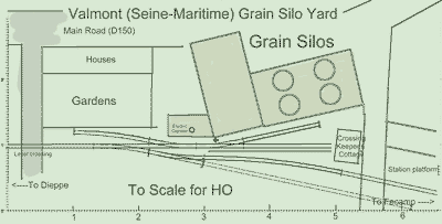
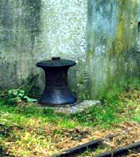
(Left, above) The prototype at Valmont, as measured by David Thomas, could easily be built in a 5’x2′ space in HO. (Right, above) Closeup shows a detail of one of the unpowered capstans used as a pulley during shunting. (Below) In this wide shot of the silo yard, you can just see the electric capstan poking up from some weeds. The “main line” is the track on the right.
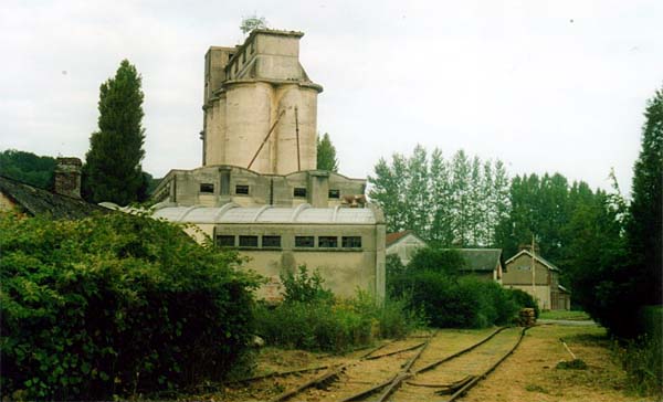
A footnote from David Thomas: “A curious footnote to the Valmont layout. The long closed line between Fecamp and Dieppe on which the prototype sits, has had its proposed abandonment overturned in the courts following a legal challenge. Abandonments have been running at an alarming level in France since the national rail network was split off from SNCF (who are now just an operating company) to form RFF (Reseau Ferre de France). Over the past few years some lines that had closed have been reopened, something which is almost impossible once the right of way has been sold off and built over. Whether trains will ever run again past the silos at Valmont remains to be seen.”
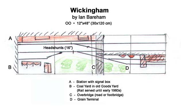
 Not a reproduction of one prototype scene, but rather a collection of scenes from East Anglia in the 1960s and 1970s is Wickingham, by Ian Bareham. Alas, most of these railside industries are gone now, as cuts to freight service have eliminated their rail access.
Wickingham is a freelance single-track terminal with a nearby grain terminal/maltings. Ian envisions “a platform with town backscenes and a road overbridge to hide the fiddle yard entrance. Or a more rural setting with a footbridge to hide the fiddle yard.
“The passenger trains would be two-car DMU (20″ long in OO scale) — Class 101’s lasted until the early 1990s. Freight service would use Class 31 or 37 units (11” long — both small enough to operate this layout).
“Until the early 1980s most towns had rail-served coal yards using the smaller 16-ton open wagons. The wagons for the grain terminal would mainly be grain cars … but the odd van could be used for bagged items.”
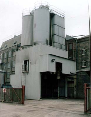
Operations will consist of push-pull passenger DMU traffic from the fiddle yard to the platform and back. Freight workings will involve pushing loaded wagons from the fiddle yard to the coal yard and hauling away empties, as well as shunting the grain terminal. Photos are typical examples of modelgenic East Anglia scenes photographed by Ian over the past 10 years.
Photos: (above right) Grain terminal silos at Great Yarmouth, Norfolk. (lower left) Typical coal yard at Diss, Norfolk — no longer rail served, but next to the station. (lower right) Class 101 DMU pulls out of Lowestoft, Suffolk, anytime from 1970 to 1990.

Boyhood memories of storage sidings in Bedford, England, inspired Trevor Simpson to adapt the design of Jack Trollope’s freelance layout, Shortover Yard, to represent a real location in Bedfordshire. Trevor explains:
“The yard used to stand between the Midland and LNWR stations, but is now a hospital car park. The car park is edged by old concrete sleepers [crossties]. A line (Bedford to Bletchley) runs by the side of the site, and the LNWR signal box can still be seen in the distance.
“The idea is that the line at the back of the layout can be used for one or two car DMU’s or a single carriage pulled by a steam locomotive. This could also be used to bring the goods wagons in and out via a cassette behind the factory. Then using the traverser the freight or passenger stock can be put into the appropriate storage siding to await its next move.
“The actual location used to have 6 sidings that fanned out through a series of points (turnouts) which started just as you passed under the road bridge. The line at the side would have been the Bedford & Hitchin branch, which at the time of my map (1925) was in fact doubled. I have vague recollections from the late 1960s and early 1970s of seeing lots of sidings on the site.”
This layout could be used unchanged to represent any of numerous cities in the U.S. which has a fan of storage sidings spreading out from under a road overbridge. One of the attractions of this design is that it can be used to play Inglenook shunting puzzles (switching games). In the case of Bedford Storage Sidings, however, a passenger railcar or short train can also run back and forth on the rear track to keep audience interest high while you ponder your next move.
Lambertville, NJ – 1852
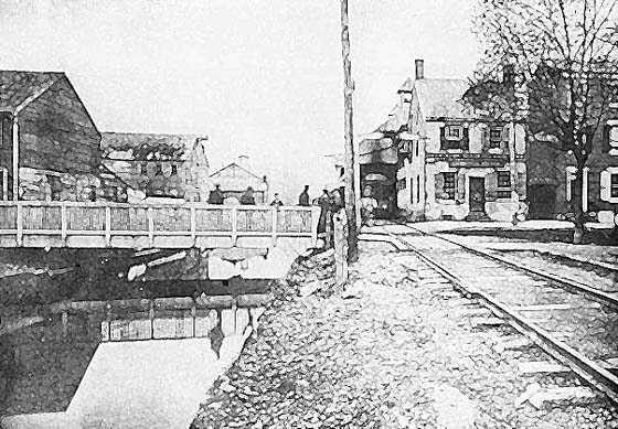
It all started when Ian Holmes acquired a used copy of Edwin P. Alexander’s long-out-of-print book, Down at the Depot. Ian was enamored of a period photo showing the Belvidere Delaware Railroad station — a 50-year-old stone house — in the pre-Revolutionary town of Lambertville, NJ. The artist’s rendering above is patterned after the photo in Alexander’s book, showing the historic white station building with a train shed behind it, alongside the peaceful Delaware Raritan canal and bridge.
“This could be the germ of a micro layout design,” Ian mused. Then he wrote me (Carl Arendt) about it, and I suggested that we each design a micro to capture the scene pictured above, to see how two different people approach the same design challenge. Here are the results:
Lambertville A:
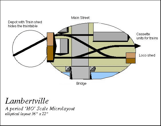
Ian’s plan takes an imaginative leap — it’s elliptical rather than rectangular, it uses a train turntable at one end and a cassette at the other to simulate through traffic, and it adds some track that did not exist in the original, but keeps the “feeling” faithful to the original scene. Ian’s goal here is to use early period trains, with passenger cars that look like stagecoaches, to pass through the scene in stately grace — from the turntable (left) , through the station scene (with a bit of switching by freight trains), and exiting via the cassette unit at the right. The cassette would then be changed out to allow another train to proceed through the scene in the opposite direction.
The photograph in Alexander’s book would have been taken from a position roughly in front of the loco shed, facing left.
Lambertville B:

My version of Lambertville treats it as a terminal, which it was until about 1855 or so. Not shown in the diagram is an 18″-long traverser with three tracks, which acts as a Fiddle Yard to introduce new trains to the layout and change old ones around. Visible trackage occupies about 4.5 feet in a simple three-track pattern that can be used for Inglenook switching games. There’s a loco shed to house a pilot loco stationed at Lambertville. The Alexander photograph would have been taken standing just above the three-way turnout, facing to the right. And in this layout, the train shed behind the station house also masks the fiddle-yard entrance.
Rolling stock on this version of Lambertville would be closer to Civil War style trains, with readily available 4-4-0 American locomotives heading trains of gaslighted carriages and freight trains of wooden boxcars with link and pin couplers. The station pilot could be any of several available HO 0-4-0 kits of small, wood- or coal-burning switch engines.
So there you have it — two very different ways to create the same scene … both of them with interesting operating possibilities and both of them occupying no more than about four square feet!
Wantage Tramway – Classic English Line
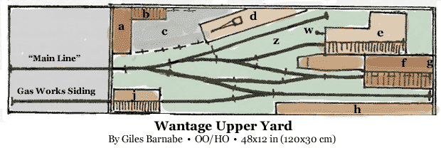
From England, Giles Barnabe has sent along an OO/HO scale version of a classic British roadside tramway. It was built in the 19th century to connect the little town of Wantage, in Berkshire, with the main line of the Great Western Railway, which passed some three miles away and provided a station at Wantage Road. The little railway followed alongside the roads all the way to Wantage. Giles’s model depicts the cramped little yard at the other end, known as Wantage Upper Yard. If ever a railway were destined to become a micro layout, this is it!
The layout plan depicts the scene pretty much as it really was from opening in 1875 to the end of passenger service during the 1920s (freight workings continued into the 1940s). There was a passenger station with a roof covering part of the low platform (f) with an arch (g) in the brick wall passing through to the station and the road beyond; a timber-built locomotive shed and workshop (e); a couple of goods sidings serving a goods platform with a small, hand-operated crane (d) and a coal and grain merchants’ wharf (h); and a line serving the town’s gas works, which was reached by running through a second engine shed (j) and into the fiddle yard on the model.
The only exception to exact reproduction is the alignment of the goods siding and loco works, which have been adjusted slightly to fit within the baseboard. For scenic purposes Giles also has added a low-relief goods store (a) and low-relief stables (b), neither of which was actually at Wantage. The cobbled goods yard is indicated at (c), the loco service coal pile and ash dump at (z), and the water crane projecting from the end wall of the loco shed at (w). The iron railings fencing in the goods yard are indicated by (+ + + +).
“In the early days,” comments Giles, “the line was kept very busy as all trains on the main line were met by a connecting service, and between times freight trains were run. Passenger stock comprised several old horse tramcars, though at one time there was a steam-powered double-deck passenger tram. At first the two other steam engines were tram locos with box-shaped bodies and skirts hiding their wheels [steam dummies], but later a couple of slightly more conventional locomotives were used–a Manning Wardle 0-4-0ST and a four-coupled well tank which dated from the mid 19th century.
“Using Peco small wye turnouts it is possible to have a loop capable of running round at least two wagons or three short ones, and also have room for a train under the platform roof, clear of the first turnout. On the far side of the loop there is only 2.5 inches of plain track–all the rest is turnouts.
“Models of the two tram locos would be simple to build in styrene and powered by SPUDs, while the steam car might be mocked up from a Mehano Brill car. A Hornby Pug is the nearest RTR loco for the saddle tank; one could substitute a square tank for the round one provided to make it more of a Manning Wardle. The last loco, ‘Jane’, could be suggested by an adapted Fleischmann Black Anna, with new boiler fittings and the cab simplified. All these are good runners and the shortest locos available–both key requirements. Plastic tramcar kits are available in the U.K. which would provide material for kitbashing the passenger stock, and normal OO freight wagons would be suitable (with a preponderance of GWR vehicles).
“Anyone contemplating building a model should refer to the books on the line by Nicholas de Courtais which are amply illustrated and demonstrate the charm of this eccentric railway backwater.”
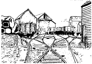
The sketch above is by Reg Wilkinson and shows his impression of the Upper Yard in the 1930s as seen from the entrance turnout. The space-saving value of wye (Y) switches is apparent. This and the photo below are adapted from Reg’s Oakwood Press book, “The Wantage Tramway” (1976).
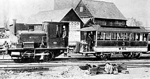
Rolling stock on the Wantage tramway was unusual, to say the least! This 1923 photo shows engine No. 7, a delightful Manning Wardle, and passenger car no. 3 showing its horsecar lineage.

Leave a Reply