The Highland Terminal
New York Central Railroad: Highland Terminal
HO Trackplan 6×1 ft (180×30 cm)
[This layout was originally published at Rich Weyand’s Tractronics website in 1994. An expanded article about the plan was published in Model Railroad Planning 2005. This article is a reprint (with updated graphics) of the original 1994 version posted on Rich’s site.]

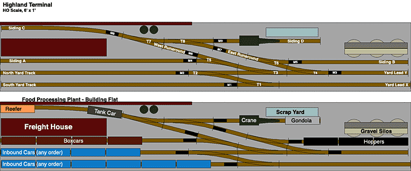
This is a track plan for a 6×1 ft HO scale switching (shunting) layout. When operating at the maximum capacity of 20 cars (10 cars coming in and 10 cars going out) it can take over an hour to complete all the switching. Incoming cars are spotted on the yard tracks by an imaginary way freight entering on Yard Lead X. The layout’s switcher must move them to the five industries on four sidings, while removing outbound cars from those sidings and placing them in the yard to be picked up.
This layout was designed for difficult switching challenges, and the track is therefore a bit denser than in prototype operation, but the design nevertheless allows for some scenery. All linear distances (track lengths, distance between track centers) are drawn to scale. For reference, every siding, yard track, etc. has been named and given a one-letter abbreviation. Turnouts are designated T1-T8, and uncoupling magnets are named M1-M9.
The layout is designed to work with 40-foot freight cars and switchers in HO. However, along with the scale drawing is information about the capacity for each length of track in cars. For example a siding with a capacity of four cars must be able to hold four cars, all of them clear of the uncoupling magnet or switch leads at the entrance to the track. Using these figures it is possible to convert the plan for any size freight car in any scale. In doing so it is vitally important to take into account all information provided about the positioning of uncoupling magnets. This was worked out carefully over time. Changing those positions may yield unintended consequences, such as cars that end up parked over magnets and cannot be recoupled.
The layout was constructed using Peco flex track and Peco turnouts (short and medium). The geometry of these turnouts makes them somewhat interchangeable, and I can no longer remember why I used the mediums where I did. I think it was primarily a matter of what I had on hand when I built this. You could convert this to all-mediums or all-shorts, but if you do so please use care to make sure all requirements for track capacity are still satisfied. Any other manufacturer’s turnouts would require some adjustments to the plan, but using track capacity as a guide should yield good results.
Finally, I’ve included a second diagram about my choice of industries, structures, and freight cars. Needless to say you should feel free to adapt these and other elements as you choose.
Peco Turnouts
Short Lefthand: T5, T6, T7
Short Righthand: T1, T4
Medium Righthand: T2, T3, T8
Short turnouts are 7.25″ long; Medium turnouts are 8.625″ long
Lengths of Flextrack
A: 34.5″
B: 21″
C: 22″
D: 18.75″
N: 33.25″
S: 41.5″
E: 6.125″
W: 6.125″
X: 23″
Y: 14″
Track Capacity
A: 5 Cars
B: 3 Cars
C: 3 Cars
D: 2 Cars
N: 5 Cars
S: 6 Cars
X: 3 Cars
Y: 2 Cars
Additional Capacity Requirements
Engine should be able to run around two cars on either runaround track.
Three cars should fit between the end of lead track Y, and T3’s switch leads.
Four cars should fit between the end of Siding C and T8’s switch leads.
Five cars should fit between the end of Lead track Y, and T5’s switch leads.
Five cars should fit between the end of Siding C and magnet M6.
Magnets
The following magnets should be positioned as close as possible to the adjacent turnout, to allow maximum clearance on siding: M1, M2, M3, M4, M5, M9
Magnet M8 should be positioned the minimum distance from the end of siding C, while still allowing three cars on the siding to clear it (about 18.5″ from end).
M6 butts up against the joint between W and T5
M7 butts up against the joint between E and T8.
Very Important: Magnets M6 and M8 should be more than two car lengths apart, so that when a string of cars is positioned over one of them for uncoupling, the couplers two cars away aren’t also uncoupling. The same goes for M5 and M7.