Wiki Articles: Small Layout Design

Small Layout Design
(Click or Browse)
John Allen on Small Layouts
Six Components of All Track Plans
Some Micro Layout Definitions
Complications Increase Shunting Fun
Easy Layouts With Threeway Turnouts
Niagara Escarpment System
‘Gorgeous’ Dutch Layout
N Scale
John Allen on Small Layouts
In Model Railroad Planning 2008, Don Mitchell quotes well-known U.S. model railroader John Allen on the subject of small layouts. John’s first layout was 43x80in (1.1x2m), a small layout even by the definition used in this site (under 24 square feet or 2.23 square meters).
Here’s what John Allen had to say in an article titled, “Some Advantages of a Small Layout,” published in The HO Monthly in 1950.
“The builder with a limited amount of time to spend on the hobby can put far more time per square foot on the small layout than he could hope to achieve on a large one.”
Another big advantage of a carefully planned small layout is achieving the greatest possible operation while spending the least amount of time on routine maintenance requirements. Says Mitchell, “During my association with John over the last decade of his larger layout’s existence, he remarked about the increasing amount of time he had to spend just keeping the layout running.”
John’s message: start small and build well. In his own words, “… plan your small railroad for operation rather than as a race track, and build it with care. You will be amazed at how much fun a small pike can be.”
Hear, hear! This web site is pretty much dedicated to exploring the fun of small layouts.
&ndash Carl Arendt
Six Components of All Track Plans
Every track plan, whether a micro or the Canadian National Illinois Central, comes down to a combination of six components. Carl has outlined all of them here, so I am just summarising them.
Pizza. Around and around and around they go…
Spur. Put a single switch on a straight piece of track, and you have a switching puzzle.
Passing Loop. Put another switch facing the first one, so the tracks split into two, then back into one.
Wye. Why not? Three switches placed together, joined frog-end to frog-end, and you have a simple turnaround track.
Balloon Track (Return Loop). A single line with a switch that goes out to the east, loops around and comes back to the west.
Switchback (Zigzag). Train goes forward into a stub-ended track, reverses up another track and then goes forward on a third track.
Reaching a little bit, we could possibly add a seventh:
Stub ends. Single piece of track with a bumper on each end.
That’s it. All railroads we see from the humble tourist train going a few hundred feet through the park to the greatest of transcontinentals is a combination of these factors. The trick to designing a successful model railroad is to combine any or all of the above into an interesting combination.
– Keith Motton, Châteauguay QC
I would say that Keith has done a good job of summarizing these. I would add a few other features, however, which are very prevalent on Micro Layouts:
Turntable. A rotating piece of track, pivoted in the center, that joins to a number of any of the above, though typically mostly to spurs, which sometimes terminate in a roundhouse.
Sector Plate. To quote Carl’s wonderful definition, “a track or tracks mounted on a board that is pivoted at one end so it can match up with several approaching tracks.”
Traverser (Transfer Table). Again to quote Carl, a &fquot;traverser (transfer table) is a series of parallel tracks on a table that can slide from side to side, providing access to several approach lines.”
Fiddle Track / Fiddle Yard. An invention of the British, I’m told — it is a hidden yard (either through or stub-ended) where one can rearrange locomotives and rolling stock so that they reenter the layout as new traffic arriving from a distant place. The fiddle yard often acts as the “rest of the world” beyond the visible layout, providing a destination for departing trains as well as a source of new traffic.
I would also take a moment to salute Carl Arendt here in his extensive publication of layouts with Fiddle Tracks, Traversers and Sector Plates — essentially popularizing a whole range of Micro Layout solutions for all of us.
– Thomas Van Hare – Oh To Fly!
Also:
Kickback. More than a spur, less than a switchback. A spur formed with two frog-end facing switches, making a spur with both a facing-point and a trailing-point component. Very non-prototypical.
– Gabriel Golden
Kickback arrangements do exist and on a larger scale than believed. Especially in Europe, where too often space is a premium, this type was moderately well used. As a matter of fact, even NASA uses kickback configurations on their Florida launch base. Google Earth shows it on the two most northerly launch platforms near Picnic Island, each on the northwest perimeter of the launchpads.
–Vincent Wesstein, the Netherlands
Some Micro Layout Definitions
There are a few words associated with Micro Layouts that new users might be interested in knowing the definitions for.
Timesaver
An arrangement of five turnouts and connecting tracks to form a runaround loop (passing siding) and three spurs. Invented by John Allen of the U.S. in the 1960s as a switching/shunting game. See Scrapbook #42 for more information. On this site, any small layout consisting of a runaround track with spurs off it is called a Tymesaver to distinguish it from Mr. Allen’s specific track configuration.
A very complete discussion of the Timesaver is found at the Model Railways Shunting Puzzles website.
Inglenook
A shunting game/puzzle involving three sidings and a headshunt (drill track). Object of the game is to assemble an outbound train with a specific sequence of cars, selected at random. Invented by Alan Wright of the U.K. in the 1980s, this puzzle generates very complex shunting problems from a minimum track configuration. See Scrapbook #69 for a variety of examples.
A very complete discussion of the Inglenook is found at the Model Railways Shunting Puzzles website.
Complications Increase Shunting Fun
Great ways to make a small switching/shunting layout considerably more fun to operate!
A shunting variation that may interest readers wanting to complicate their life is the aviation or other highly flammable fuel siding. The rules for operating such a siding for shunting puzzle purposes (and roughly for reality) are:
- The locomotive may never enter the fuel loading siding. If neccessary the tankers must be pushed into the right place in the siding (or retrieved) using other wagons.
- The fuel wagons must never be coupled directly to the locomotive, or directly to the guards van (caboose to those on the other side) but there must always be at least one wagon between at each end (the “barrier wagon”).
- As far as possible the locomotive must not run directly alongside fuel wagons (empty or full) in adjacent sidings.
– Alan Cox, UK
Have a road cross one of more of the sidings (a “level crossing” in UK), with a rule that trains cannot block road traffic for longer than 10 minutes at a time. (This one is easier in the U.S. where ungated crossings are common. Many are protected only by the familiar crossbuck signs.)
(Comment by Alan — Ungated crossings are actually not uncommon in the UK for low usage lines crossing low usage railways. You can find equivalent cases and indeed rules about crossings. Also found are gated crew operated crossings, although the old freight ones where the driver stopped to open the gate and after the train passed the guard at the other end closed them have I think now gone for good. (That took some good judgement from the crew or the guard had a long walk.)
Another problem can be added by placing all three sidings on a car ferry (a la Jack Trollope) s— the new rule being that the locomotive cannot board the ferry, but must use one or two “idler cars” as a handle to pick up wagons parked near the rear of the ferry.
(Comment by Keith — There is also the issue of not “tipping the boat” when you use a car ferry – the load must be kept balanced, no more than one car difference between the two tracks. Prototypes often got flipped when an inexperienced man pulled the whole rake of cars off one side of the ferry.)
(Comment by Alan — That’s historically correct for the UK with bridges. Various sites had weak bridges that wagons were pushed over (or just given a good shove which is hard to model below O gauge…) and signs indicating “Locomotives must not pass this point.” In fact I think there’s even a Thomas the Tank engine story about it and what happens when they do pass the sign. If I remember rightly there were also sidings handled this way where the clearance was too low for a locomotive due to overbridges or handling equipment.)
Some people also use “situation cards” — instructions that override the switch list, replicating emergencies faced in real life, such as “Engine drops a rod. Swap for another” or “Hotbox on boxcar #___, place on house track for repairs”, etc. You pull one from the deck whenever a timer bell rings.
– Carl Arendt, USA
The Thomas the Tank Engine story Alan recalls was actually with mine shafts, but the principle remains. These car ferries were also found in the USA with, I presume, similar rules. In fact, someone is actually building a true-to-scale (1:87) model of the CNJ Bronx Terminal yard. He’s busy doing other things right now, but he does build all his trackwork by hand…
– Vincent Wesstein, the Netherlands
Easy Layouts With Threeway Turnouts
Q. I have a couple Shinohara 3-way turnouts, one Shinohara curved turnout, several lengths of Peco flextrack and Atlas Custom Line #4 turnouts and track sections, all in HO scale. I’ve been fascinated with shelf layouts as they provide more track per square foot than other layout designs. The problem is to combine what I have into a viable shelf layout. I would appreciate any design suggestions you may have to utilize my existing track. – P.S.
A. There are a good many layouts on my website that would use at least one of your three-way turnouts. The only one I can think of that uses more than one 3-way is Bob Moroch’s Different Timesaver in Scrapbook #54. Bob uses up to four of them! His basic design, with two 3-ways, can be augmented with other switches in lots of ways to add to the operating fun.
Brian Wilson’s excellent On30 shelf line, Moore’s Yard, also makes a good basic plan that can be extended in lots of ways. Photos are in several places on the site, including Scrapbook #63a and on Brian’s website (linked in the article).
Browsing through the “Shelf Line” section of the Micro Layout Design Gallery should ignite lots of good ideas. A couple that come to mind, using at least one 3-way switch, are:
- Threeway Points Mill (three different designs using 3-way switches really well)
- Smallsbury Parva (excellent basic plan, includes an Inglenook)
- King’s Pancreas (full of track and offers passenger running)
- Folding Way Terminal (only four-feet long excluding fiddle yard)
- Lesser Titchfield (good basic shunting layout)
- TF Industries (dense trackage, great operations in small space)
… and there are more. Find them in the Linked Index of the Gallery. To get a complete rundown on the whole site, use the Google Search box on the home page, and search “three-way.”
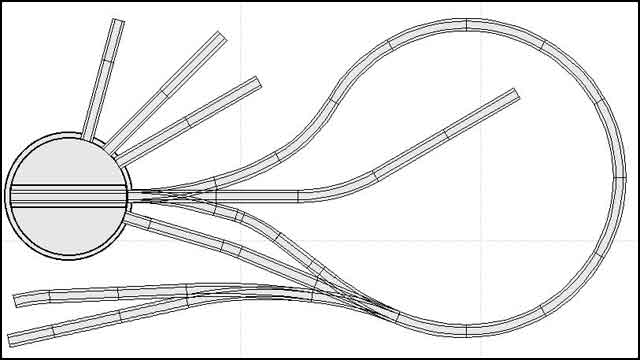
Finally, I can’t resist attaching a layout I designed for a friend just last week. It uses Roco N track for HOn30 scale (to fit in a commercial storage box) but would work fine in HO standard-gauge as well. Coincidentally, it requires two 3-way switches and a curved turnout!
– Carl Arendt

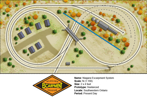
Niagara Escarpment System
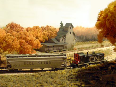
While not specifically based on any particular railroad, the Niagara Escarpment System does owe its genesis to the inspiration gained from studying the Guelph Junction Railway — a small branch line operation managed by the Ontario Southland Railway.
Website is here.


‘Gorgeous’ Dutch Layout
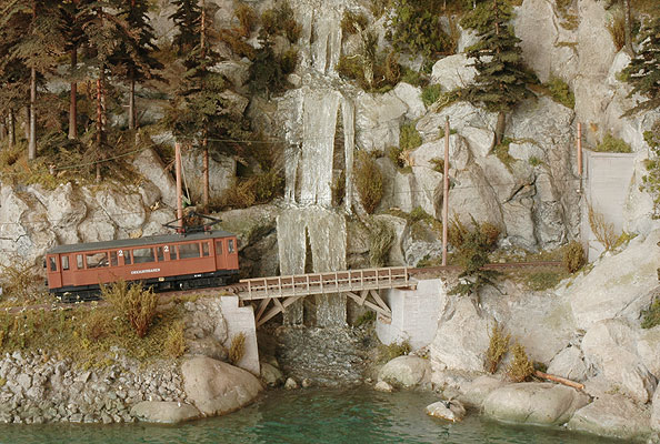
It’s not a micro … but it’s gorgeous! I knew these guys were building this gem for awhile, but they didn’t have English pages to tell the rest of the world. I helped them out in translating the Dutch pages into English, but be prepared to find some bad grammar and incorrectly translated words ;-). Here’s the page.
– Vincent Wesstein, the Netherlands

N Scale
Q. N Scale is 1:160, with a 9mm gauge, right?
A. Mostly, but:
- British N Scale is 1:148, still on 9mm track, to make up for British railways’ small loading gauge.
- But the British finescale group, the 2mm Association, models at a scale of 2mm=1ft, with a gauge of about 9.5mm.
- Japanese N Scale is 1:150, still on 9mm track, mostly representing 42in gauge railways.
Nn3 uses Z gauge (1:220 on 6.5mm gauge) track and mechanisms to represent narrow gauge railways in N Scale, typically modelling 3ft gauge prototypes, but actually scaling out closer to 42in gauge (used by railways in Japan, parts of the former British Empire, the surviving San Francisco cable car lines, and some former streetcar systems such as the Los Angeles Railways and Denver Tramways).
N Scale track is used for HOn30 modeling (30in gauge in HO scale), which is often a convenient proxy for either 2ft gauge (typically Maine prototypes) or 3ft, though 30in gauge railways have in fact existed. The 9mm gauge is also in use for TT9 (UK, 3mm=1ft, used for 3ft prototypes), Sn2, On18 (U.S.), On15/O9 (U.K.), and Gnine modelling.